All the wiring schemes and examples are based on an Arduino One and an 8-pins ESP8266 module also know as ESP-01. Arduino pins 6 and 7 will be used as a second serial port using SoftwareSerial library as described here.
| Schema | Power | RX | TX |
|---|---|---|---|
| 1) Basic | N | N | N |
| 2) Powering with diodes | Y | N | N |
| 3) Powering with Zener diode | Y | N | N |
| 4) Powering with voltage regulator | Y | N | N |
| 5) RX level shifter with resistors | N | Y | N |
| 6) RX level shifter with diode | N | Y | N |
1) Basic
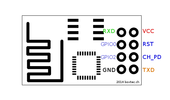
Here are the ESP-01 pins.The most basic connection scheme is this.
Wiring
- Arduino 3.3v power > breadboard red power rail
- Arduino GND > breadboard black ground rail
- ESP8266 GND > ground rail
- ESP8266 VCC > power rail
- ESP8266 CH_PD > power rail
- ESP8266 TXD > Arduino Digital Pin #6 (RX pin using software serial)
- ESP8266 RXD > Arduino Digital Pin #7 (TX pin using software serial)
- A 100uF (or larger) capacitor helps to absorb current spikes
This schema has three main problems:
- Power source: Arduino boards are typically powered at 5V while ESP8266 needs a 3.3V power source. The ESP can draw up to 250mA while the Arduino Uno 3.3V output pin can provide only 50mA. A capacitor can help but it's not enough.
- RX: The 5V Arduino TX serial output needs to be shifted to the 3.3V ESP RX input. However, simple prototypes can be built without this because the ESP has a built in protection.
- TX: The 3.3V ESP TX output should be enough for the 5V Arduino digital input. A reliable project may need a level shifter.
The next wiring schemes will show different approaches to provide a reliable 3.3V power source to the ESP.
2) Powering with diodes
Since the Arduino 5V pin can provide 200mA we can use this to power the ESP. This schema is very cheap and simple allowing to use simple and cheap diodes to convert the 5V to 3.6V. Suitable diodes are the 1N4148 (300 mA) or the 1N4007 (1 A).3) Powering with Zener diode
An alternative cheap approach is to use a 1N5226 3.3V Zener diode to power the ESP as described here.4) Powering with voltage regulator (LM1117/LD1117)
Several cheap 3.3V regulators are available on the market. A very common and cheap one is the LM1117 (or LD1117). With such regulator you can convert the 5V power used for Arduino to the 3.3V needed by the ESP.An AMS1117 module is also a great choice.
A generic voltage regulator like the LM317T can be used as described in this post.
5) RX level shifter with resistors
The 5V output from the Arduino TX pin can be shifted to 3.3V using a resistor voltage divider.In this schema I have used three 220 Ohm resistors for an output current of 7.5 mA.
6) RX level shifter with Diode
You can use a 1N4148 diode on the Arduino TX pin as well to lower the voltage of the signal.
Putting all together
Now pick your preferred schemes to build your perfect Arduino/ESP wiring.
References
5V to 3.3V Logic Level Shifting


إرسال تعليق